
Conveyor fabrication guide
Conveyor Frame Drawings: Loads, Interfaces and Fabrication Checks
Matching the mounting holes is only part of getting a conveyor frame to fit. Roller height, support positions and the space needed to remove a worn roller can all change the detail you need on the drawing.
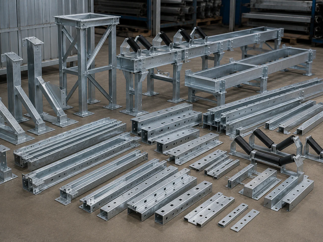
What does “conveyor frame” include?
The term can mean a small frame carrying a set of rollers, a mounting bracket, or a length of fabricated conveyor structure. A quotation for one is not directly comparable with a quotation for another. Mark the supply boundary on the general arrangement and give each supplied item a part number.
| Item | Drawing focus | Supply check |
|---|---|---|
| Idler frame | The roller arrangement, shaft-end supports, trough geometry and mounting points on the stringers. | State whether rollers and retaining parts are included. |
| Bracket or support | The local connection: hole pattern, contact faces, adjustment and the item being supported. | Identify left- and right-hand versions and any loose plates or fasteners. |
| Structural module | The arrangement of members, spans, support points, bracing and connections to adjacent modules. | List legs, walkways, guards and other attached items separately. |
A picture of an assembled conveyor does not establish what comes with the steelwork. If rollers, bearings, guards, anchor bolts or site installation are part of the enquiry, list them. If they are supplied by someone else, include the interfaces they impose.
For carrying, return and impact arrangements, see the conveyor idler selection guide. This article deals with the supporting fabrication and its drawing package.
Give each drawing a clear job
A general arrangement is useful for orientation, but an overall length and width will not define a fabrication. The workshop also needs the member details and the dimensions that connect it to the rest of the conveyor.
- General arrangement
- Shows where the module sits: conveyor centreline, elevations, belt direction, support locations and neighbouring equipment.
- Interface drawing
- Controls the connection to another item: hole centres, mating faces, datum references, tolerances and clearance envelopes.
- Fabrication and assembly drawings
- Define the parts to make and join: sections, plate thicknesses, material grades, welds, connections, finish and item numbers.
Use the same reference points across the package. For a replacement, identify which site dimensions have been checked and which come from an old drawing. A worn or bent frame should not silently become the dimensional master.
Check revision agreement before sending the files. If a model shows one hole position and the drawing shows another, state which document controls and resolve the difference before manufacture. A supplier should be able to trace every quoted item back to the agreed revision.
Put loads where they act on the structure
“Suitable for this belt width” is not a structural design basis. The same width can be used with different material loads, spans and support arrangements. Show the support positions and how the loads enter the frame.
Have the responsible engineer identify the applicable cases. Depending on the module, these may include the structure and equipment weight, belt and conveyed material, loading-point impact, drive or take-up reactions, maintenance loads and site environmental loads. They do not necessarily act together at their individual maximum values; the design basis must define the combinations.
For each supplied load, give its magnitude, units, direction and point or length of application. Distinguish operating loads from factored design values. A single “total load” leaves the fabricator unable to tell whether it is spread along the module or concentrated at one connection.
Support spacing, restraint and permissible deflection need the same attention as strength. An overall span without its support conditions is incomplete. Agree who supplies the structural calculations, connection design and any foundation information; a fabrication quotation does not by itself establish those responsibilities.
This checklist does not select beam sections or assign a safe working load. Those decisions require the project’s engineering design and acceptance criteria.
Why can the holes match and the frame still not fit?
Consider a replacement idler frame with the correct mounting-hole centres. If its roller supports sit higher than the existing ones, or accept a different shaft-end detail, it may bolt to the stringers without putting the rollers in the required position. Hole centres alone do not control the complete interface.
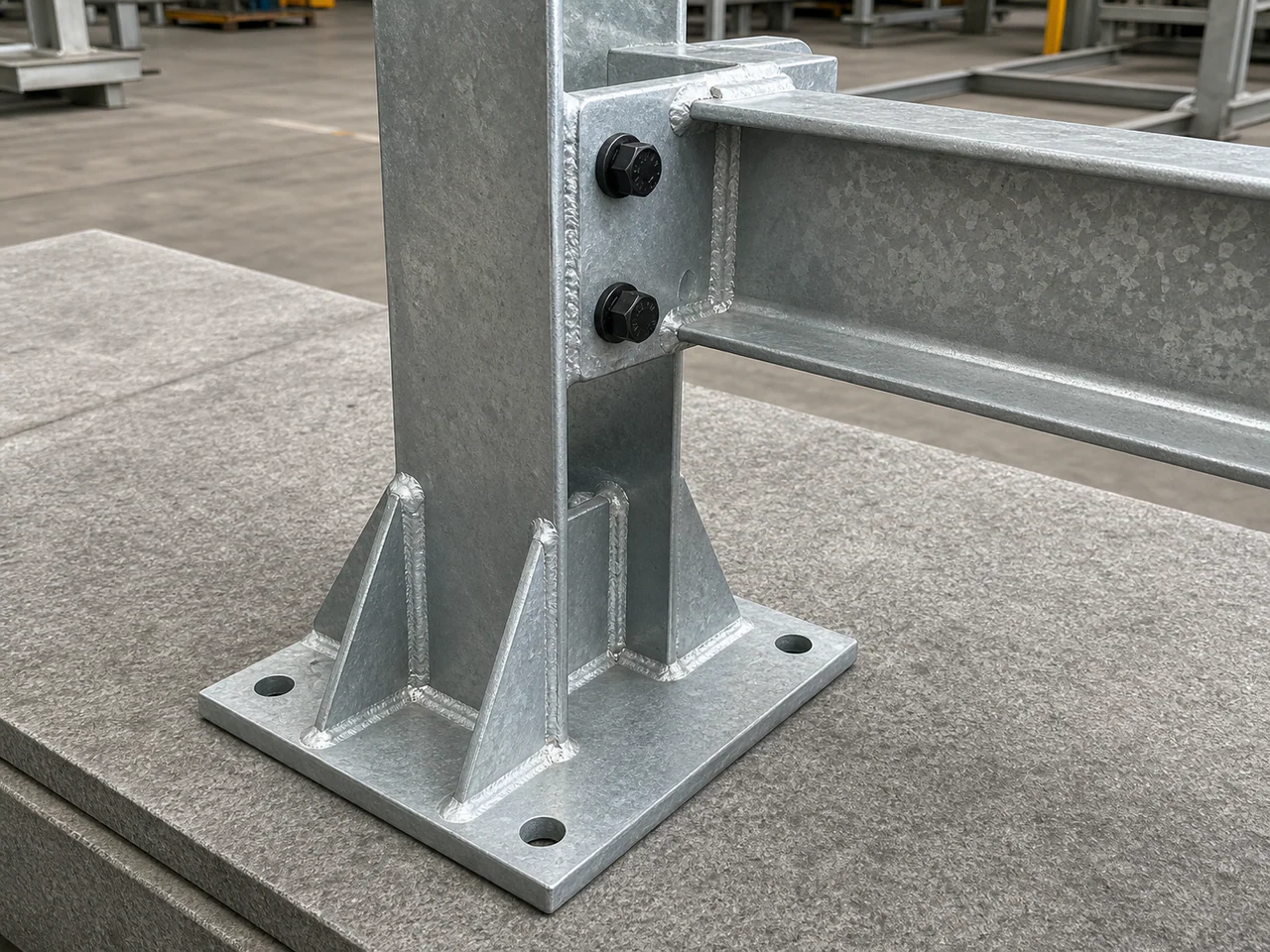
Read the connection in three dimensions
- Position: locate mounting faces, holes and roller supports from agreed references, including height and orientation.
- Engagement: define shaft-end slots or other retention details, fasteners and any adjustment travel.
- Clearance: check the roller, belt, guards and adjacent members, plus the space for fitting tools and withdrawing parts.
Show whether a bracket is handed and which way it faces on the conveyor. On a symmetrical-looking frame, a small offset can make the two ends different. Sections and detail views often communicate this more clearly than another overall dimension.
Review the maintenance envelope with the equipment owner. A roller that fits during workshop assembly may be difficult to remove once a walkway or guard is installed. Installation and maintenance arrangements must retain the required guarding and access provisions; clearance is not a reason to omit them.
Tie the final dimensions to the fabrication sequence
Welds and distortion
Specify the joints and weld requirements, including any inspection needed. Welding can move a frame out of its intended geometry. Weld placement, deposited weld volume, fit-up and sequence all affect distortion, so the fabrication review should address how the critical faces and hole positions will be maintained.
Adding weld metal is not a general remedy for an uncertain design. Changes to weld size or joint detail need approval against the design requirements. Identify the dimensions that must be verified on the completed fabrication, rather than relying only on checks made before welding.
Machined mounting faces
If a mounting pad or bearing interface needs machining, show its extent, finish and relationship to the other interfaces. Agree the final measurement condition and the proposed operation sequence. Do not assume that every plate surface will be machined because one interface has a close tolerance.
Coating and protected surfaces
“Painted” or “galvanized” leaves the coating specification open. Identify the required system and acceptance requirements, together with surfaces to mask or leave untreated. Clarify whether mating dimensions apply before or after the finish. Include any coating-related fabrication details in the approved drawing package before production starts.
Our welding and fabrication page describes the manufacturing scope available for review. The drawing and order define the requirements for the particular frame.
Decide what will be assembled and checked before dispatch
A module can leave the workshop as a welded assembly, bolted sections or a kit of parts. State the required condition and any transport limits early. Show site joints, loose connection plates, fasteners and any parts that must stay together.
Where trial assembly is required, define its extent: one module, adjoining modules, or the frame with specified mating components. Agree who supplies those components. Checking a frame against a drawing is different from physically fitting it to the buyer’s equipment.
Build the inspection list around the interfaces: mounting-hole position, support height, alignment, specified flatness and the relevant overall dimensions. Identify the reference features, tolerances, inspection extent and required records. Add material, weld and coating records where the order requires them.
For dismantled assemblies, use item numbers and agreed match marks that remain identifiable through finishing and packing. Cross-reference them to the assembly drawing and packing list. This gives the receiving team a way to distinguish a missing item from a similar-looking part intended for another module.
What to send for a conveyor frame quotation
Start with the current drawings and an itemised supply list. Mark unresolved inputs, and distinguish a budget enquiry from a package ready for manufacture.
- Current documents
- GA, fabrication drawings, controlled interfaces and a matching model if available. Include revision, units, item numbers and quantities.
- Design inputs
- Approved spans and support locations, applicable load cases and combinations, design criteria and responsibility for calculations.
- Supplied condition
- Material, weld requirements, machining, coating, loose items, assembly extent and any buyer-supplied components.
- Acceptance and delivery
- Inspection characteristics and records, trial-assembly scope, match marking, packing limits, destination and required date.
ROCKVANTA reviews conveyor frames, brackets and structures against the supplied layout, loads, interfaces and manufacturing requirements. When comparing quotations, check the included parts, finish, assembly condition and inspection records alongside the price.